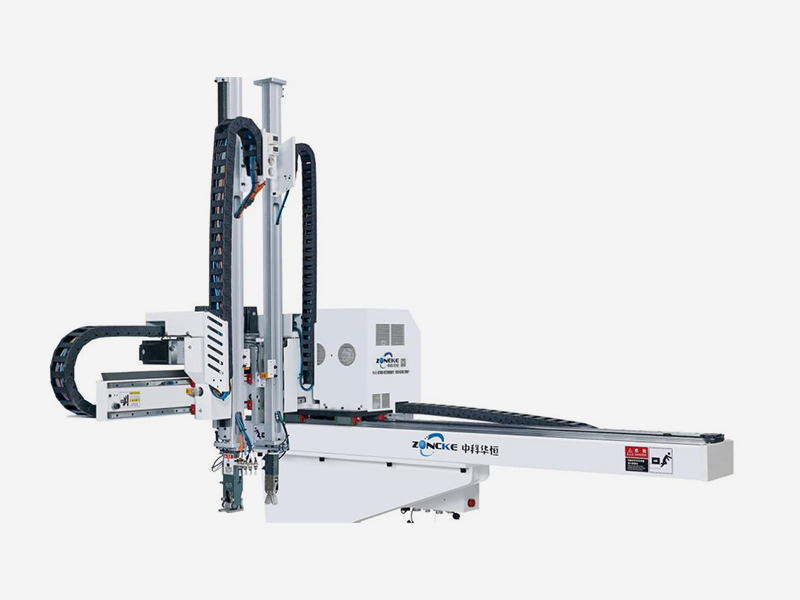
How to match the robot arm to the injection molding machine?

Matching a robot arm to an injection molding machine involves several key steps to ensure compatibility, efficiency, and safety. Here's a guide to the process:

1. Determine the Application and Functionality
Pick-and-Place: If the robot arm is used to handle parts (inserting or removing), assess the robot's reach, payload capacity, and speed.
Molding Cycle: Consider the molding machine’s cycle time and how the robot arm will integrate with it to avoid delays.
Part Complexity: If the parts are complex in shape, the robot arm must have a high degree of freedom or specialized tooling (like grippers or suction cups).
2. Payload Capacity and Reach
Payload Capacity: Ensure the robot arm can handle the weight of the parts being picked or placed. This depends on the size and material of the molded part.
Reach: The robot must have a sufficient reach to access the injection molding machine’s mold area and unload parts efficiently without obstruction.
3. Coordinate System Integration
Machine Coordination: The robot arm’s coordinate system should align with the injection molding machine’s (IMM). This includes setting up the robot to pick parts from specific locations (e.g., the mold cavity or cooling area).
Synchronization: The robot must be synchronized with the IMM’s cycle. Typically, a signal is sent when the mold opens, and the robot arm must then act quickly to remove the part. This might involve PLCs (Programmable Logic Controllers) to synchronize cycles.
4. Interface and Communication
Controller Compatibility: The robot’s controller should be able to communicate with the IMM's control system. This might require integration via common protocols such as Modbus, Ethernet/IP, or Profinet.
Cycle Time Coordination: Ensure that the robot is programmed to begin its operation once the injection molding cycle completes, ensuring smooth part removal and minimal downtime.
5. Safety Considerations
Safety Enclosures: Depending on the robot’s speed and movement, safety barriers or light curtains should be installed to protect operators from moving parts.
Emergency Stops: Integration of emergency stop functions between the IMM and the robot arm is crucial for overall safety.
6. End Effectors
Grippers or Suction Cups: Choose the correct end effector based on the part geometry. For small or delicate parts, vacuum-based grippers may be more suitable, while larger, sturdier parts may need mechanical grippers.
Customization: If parts are irregularly shaped, custom tooling may be required to ensure secure and efficient handling.
7. Software Integration
Robot Programming: Set up the robot programming to match the cycle of the IMM. This includes fine-tuning the movements for precision, speed, and avoiding collisions.
Monitoring & Adjustment: Some systems allow remote monitoring of both the IMM and robot, so adjustments can be made in real time if needed.
8. Physical Installation
Mounting the Robot: Install the robot on a suitable mounting platform near the IMM. A common method is to mount the robot on the IMM itself or on a separate pedestal.
Cable Management: Properly route cables and hoses (if any) for the robot arm to ensure they don’t interfere with the IMM’s movements and remain protected from potential damage.
9. Cycle Testing
Dry Runs: Perform dry runs to check the robot's interaction with the IMM. Test the robot’s movements, speed, and efficiency in a controlled manner before starting full production.
Adjustments: Make any necessary adjustments to the speed, cycle times, or tooling based on the dry run results.
10. Optimization and Maintenance
Optimization: After installation and initial testing, continually monitor the system to ensure that cycle times are optimized and downtime is minimized.
Maintenance: Regular maintenance and calibration of both the robot arm and injection molding machine are crucial for long-term reliability and performance.
By carefully matching the robot arm's capabilities with the injection molding machine’s requirements, you can achieve improved efficiency, reduced cycle time, and greater consistency in part handling.


